Fiber Optic Cable Bend Radius: Why It Matters and How to Get It Right
Every fiber optic cable has a number that determines whether it survives a gig or comes back dead: its minimum bend radius. Exceed it once and you might get away with it. Exceed it repeatedly, around truss corners, over stage decks, wound tight on undersized reels, and you’re stacking up loss that kills signal integrity or fractures the glass outright.
This guide covers what bend radius actually means, how it differs across cable types, where production crews most commonly violate it, and how to test for damage when you suspect a bend is the culprit.
What Is Bend Radius?
Bend radius is the minimum radius a cable can be bent without degrading optical performance or damaging the fiber. It’s measured from the center of the curve to the inside edge of the cable, not as a diameter. A cable with a 40mm minimum bend radius can wrap around a cylinder with a 40mm radius (80mm diameter). Anything tighter risks damage.
There are two specifications that matter:
- Unloaded (static) bend radius — the minimum radius when the cable is installed and at rest. No tension, no pulling force. This is the tighter of the two numbers.
- Loaded (dynamic) bend radius — the minimum radius while the cable is under tension during deployment. Pulling cable through conduit, paying out from a reel, dragging across a venue floor. This number is always larger, typically 1.5 to 2 times the unloaded spec.
The loaded spec is the one that matters most in production. Cable is under load constantly during deployment: getting pulled, stepped on, run over by road cases, and bent around obstacles while someone hauls on the other end. If you only remember one number, remember the loaded bend radius.
Why Bend Radius Matters in Production
Fiber optic cable transmits data as light traveling through a glass core. The light stays in the core because of total internal reflection: the cladding around the core has a lower refractive index, so light bounces back inward at shallow angles. Bend the cable and you change those angles.
Macro-Bending Loss
When you bend fiber past its minimum radius, light hits the core-cladding boundary at angles that are too steep for total internal reflection. The light escapes through the cladding and is lost. This is macro-bending loss, and it’s the primary failure mode from bend radius violations.
Each bend adds insertion loss to the link. A single gentle violation might add 0.1–0.5 dB. Sounds small, but it’s cumulative. A 300-meter run through a venue with four or five tight corners can stack up 1–2 dB of bend loss on top of the cable’s baseline attenuation and connector loss. On a multimode link running close to its distance limit, that’s enough to push you from clean signal to errors.
Single mode fiber is more sensitive to bending than multimode. The smaller core diameter (9 μm vs 50 μm) and tighter propagation angles mean SM fiber sheds light into the cladding faster at a given bend radius. A bend that causes 0.2 dB of loss in multimode might cause 0.5 dB or more in single mode at the same radius.
Fiber Fracture
The glass fiber inside the cable is strong under tension but brittle under sharp bending. Go past the minimum bend radius, especially under load, and you can fracture the glass. Unlike bend loss, which is often reversible if you straighten the cable, a fractured fiber is permanent. The cable is dead. On a show, that means switching to a spare or re-routing on the fly.
Fracture doesn’t always happen at the moment of the violation. Repeated bending cycles at or near the minimum radius create micro-cracks in the glass that grow over time. A cable might survive one tight wrap around a truss corner, then fail six months later during load-in when that same section gets bent again. This is why tactical cable built for production uses aramid yarn and steel armor: not to prevent bending, but to prevent the cable from being bent tighter than the fiber can handle.
Bend Radius Specifications by Cable Type
Not all cable is built the same, and bend radius varies with construction. Here’s how our tactical cable lines compare:
| Specification | Standard Tactical | Super Tactical |
|---|---|---|
| Cable OD | 4.8 mm | 7.2 mm |
| Armor type | Aramid yarn | Steel interlocking armor + aramid |
| Unloaded bend radius | 25 mm | 45 mm |
| Loaded bend radius | 40 mm | 70 mm |
| Crush resistance | Moderate | High |
| Fiber count | 2–4 fibers | 2–4 fibers |
A few things to note:
Larger cable = larger bend radius. The Super Tactical line uses steel interlocking armor for crush resistance, which makes the cable stiffer and increases the minimum bend radius. You gain durability at the cost of flexibility. The cable that survives being run over by a forklift is also the cable you can’t wrap tightly around a 2-inch truss chord.
Armor type is the primary driver. The fiber itself (whether Corning SMF-28 single mode or OM4 multimode) has a bare fiber bend radius of about 5–10 mm. The cable construction (jacket, strength members, armor) is what determines the assembled cable’s bend radius. Steel armor raises it considerably. Aramid-only construction keeps it tighter.
Single mode vs multimode matters at the optical level, not the mechanical level. Both SM and MM versions of the same cable construction have the same mechanical bend radius. But single mode fiber experiences more optical loss per bend, so while you can mechanically bend an SM cable to the same radius as MM, the SM link will lose more signal at that bend. In practice, treat single mode runs with even more care around corners and transitions.
Common Bend Radius Violations in Production
If you’ve worked in live production, you’ve seen every one of these. Most crews don’t even register them as problems until the fiber tester comes out and the link budget doesn’t add up.
Tight Turns Around Truss Corners
Fiber run along truss almost always gets bent around the corner where vertical meets horizontal. The truss chord is typically 50mm diameter. Cable wrapped tight against it sits right at the loaded bend radius for Standard Tactical and well below it for Super Tactical. Add a tie-wrap cinching the cable against the chord and you’ve created a permanent macro-bend.
Fix: Use saddle clips or Velcro wraps that hold the cable loosely against the truss, allowing it to take a natural curve. Leave 150–200mm of slack at each corner so the cable can arc rather than crease.
Cable Crushed Against Stage Deck Edges
Cable running off the edge of a stage deck and dropping to the floor below bends at a sharp angle against the deck edge. If a road case or monitor wedge pushes the cable against that edge, the bend tightens further under load.
Fix: Cable ramps or edge protectors at every deck transition. A foam pool noodle zip-tied to the deck edge is better than nothing.
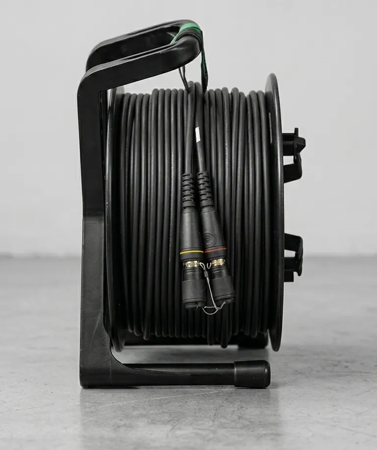
Undersized Reels
Winding cable onto reels that are too small for the cable diameter is one of the most common sources of cumulative bend damage. Every wrap is a bend, and the cable sits at that bend for days or months between shows. Over time this causes set memory in the jacket and sustained micro-bending across the full cable length.
Fix: The reel core diameter should be at least 20 times the cable OD for storage. For Standard Tactical (4.8mm OD), that’s a minimum 96mm core — roughly a 4-inch reel core. For Super Tactical (7.2mm OD), you need a minimum 144mm core. Most commercial cable reels meet this easily, but beware of coiling cable by hand into tight figure-eights or wrapping it around your elbow.
Sharp Conduit Turns
Pulling fiber through conduit with tight 90-degree bends is a double violation: the cable bends past its minimum radius and it’s under tension (loaded) while it happens. Standard EMT conduit bends are typically around 100–150mm radius, which is fine for Standard Tactical but marginal for heavier cable. The problem comes when multiple 90s stack up in a short run, or when someone bends conduit by hand and creates a kink instead of a sweep.
Fix: Use sweep 90s or 45-degree fittings. Limit any conduit run to two 90-degree bends maximum. For permanent installs, specify the conduit bend radius to exceed the cable’s loaded spec by at least 50%.
Best Practices for Maintaining Bend Radius
Most bend radius violations come down to cable management discipline:
-
Route cables with sweeping turns. If you can’t make a turn in a single smooth arc, add slack so the cable curves naturally. Sharp corners are never acceptable.
-
Use proper reel sizes. Match reel core diameter to cable OD: minimum 20x the OD for storage, 30x for long-term storage.
-
Cable ramps at every transition. Stage edges, dock doors, floor-to-wall transitions. A $30 cable ramp prevents a $500 cable repair.
-
Strain relief at every termination point. Neutrik opticalCON connectors handle field abuse, but the cable behind the connector still needs support. A cable dangling from a patch panel with its weight pulling on the bend at the connector is a slow-motion failure.
-
Never tie-wrap fiber tight to structure. Velcro wraps, hook-and-loop straps, or loose tie-wraps only. If you can’t slide the cable back and forth inside the tie point, it’s too tight.
-
Train your crew. The best cable in the world won’t survive a crew that doesn’t understand bend radius. Two minutes during load-in prevents hours of troubleshooting.
How to Test for Bend-Related Loss
When a fiber link has higher loss than expected, bending is one of the first things to check. Two tools handle this well:
OTDR Testing
An optical time domain reflectometer (OTDR) from manufacturers like Fluke Networks or EXFO sends a pulse of light down the fiber and measures reflections over distance. Bend loss shows up as a localized drop in backscatter level at a specific point along the cable. Unlike connector loss (which shows a reflection spike), bend loss is a smooth downward step with no reflection. A skilled operator can identify each bend, measure the loss it adds, and pinpoint the distance along the cable where the violation sits.
If you see a bend loss event over 0.3 dB, investigate. Events over 0.5 dB indicate a serious violation that needs correction. Multiple smaller events (0.1–0.2 dB each) can add up to a link-budget-busting total.
For more on fiber testing methodology, see our guide: How to Test Fiber Cable.
Visual Fault Locator
A visual fault locator (VFL) is a visible red laser source, typically 650 nm, that you inject into one end of the fiber. At any point where the fiber is bent past its minimum radius, red light leaks through the cladding and jacket and is visible to the naked eye. Walk the cable run with the VFL active and look for red glow points. Each glow point is a bend that’s shedding light.
VFLs are cheap, fast, and don’t require any training to interpret. They won’t tell you the loss in dB, but they’ll show you exactly where the problem is. Every fiber tech should carry one.
Frequently Asked Questions
What is the minimum bend radius for fiber optic cable?
What happens if you bend fiber optic cable too much?
Does armored fiber cable have a different bend radius?
How do I know if a bend has damaged my fiber?
The Bottom Line
Bend radius is one of those specs that’s easy to ignore until it costs you a show. The physics are simple: bend fiber too tight and light escapes, loss increases, and eventually glass breaks. The fixes are just as simple: proper reel sizes, sweeping turns, cable ramps, and a crew that knows the limits.
Every meter of tactical fiber cable we build at Fiber is designed for production deployment, but no amount of armor compensates for wrapping cable around a truss corner like it’s copper. Know your cable’s bend radius and respect it.